
Industrial networks are designed with one priority above all else: availability. Any component added to the production network is therefore met with understandable caution. We often encounter OT teams that are hesitant to deploy passive Fiber TAPs because they fear introducing a potential point of failure into critical fiber links.
In practice, those concerns are rarely about the TAP itself. They are about understanding how optical networks behave and ensuring that installations follow established engineering practices.
When deployed correctly, passive Fiber TAPs provide highly reliable, maintenance-free network visibility without introducing operational risk. Unlike SPAN ports or active inline devices, passive Fiber TAPs require no power, have no software, and contain no active electronics that can fail.
Following two best-practice principles is typically all that's needed to ensure reliable long-term operation.
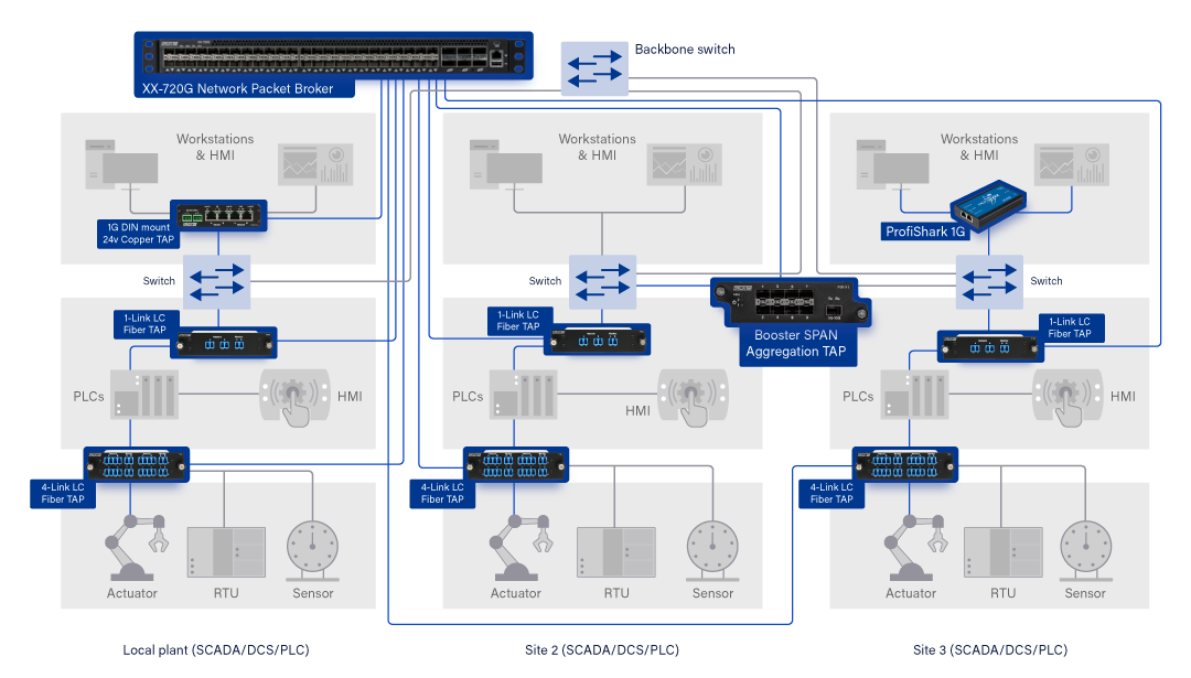
1. Design with sufficient optical budget
Every fiber connection has a finite optical power budget: the difference between transmitter output power and the minimum receiver sensitivity. Every component in the link consumes part of that budget, including:
- Fiber attenuation
- Connector losses
- Splice losses
- The insertion loss introduced by the Fiber TAP
Before selecting a TAP split ratio, calculate the total optical budget and leave a generous engineering margin. A reserve of approximately 2–3 dB is considered good practice to accommodate long-term changes in the installation. We wrote an article about this topic. (Profitap Insights)
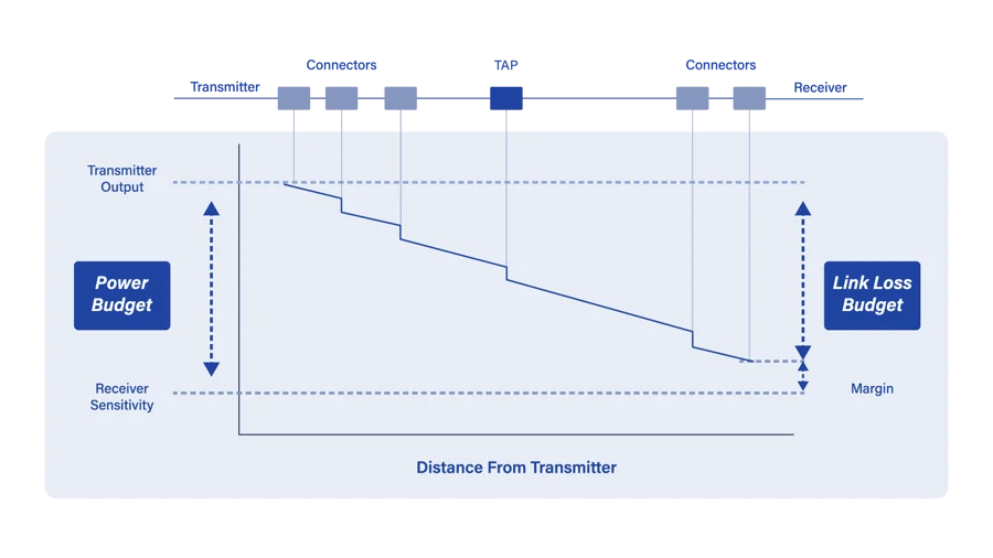
This safety margin accounts for factors such as:
- Normal aging of optical transceivers and laser diodes
- Small connector and splice losses
- Future maintenance activities
- Manufacturing tolerances
- Receiver sensitivity differences between devices
Selecting the correct split ratio is equally important. Lower monitoring ratios introduce less attenuation into the production path, while higher monitoring ratios provide stronger signals to monitoring tools but consume more optical budget. Choosing the appropriate ratio should always balance monitoring requirements with available optical margin. Article: Optical Budget & Split Ratios in Fiber Network Monitoring
If optical budget becomes limited, consider alternatives such as:
- Selecting a different split ratio
- Using single-mode fiber where appropriate
- Deploying regeneration TAPs when signal amplification is required. (Profitap Insights).
2. Installation quality determines long-term reliability
Even a perfectly calculated optical budget can be compromised by poor installation practices.
Most fiber-related problems encountered in production environments are caused by physical installation issues rather than the TAP itself.
Keep connectors clean
Dust remains the number one cause of unexpected optical attenuation.
Before connecting any fiber:
- Inspect every connector end-face
- Clean connectors using appropriate fiber cleaning tools
- Reinspect before mating
- Keep dust caps installed on unused ports
Using a fiber inspection microscope is considered industry best practice and helps prevent many installation issues before they occur. Profitap's installation guidelines also recommend cleaning connectors as the first troubleshooting step when signal quality is affected. (Profitap Knowledge Base)
Respect the minimum bend radius
Fiber cables should never be forced into tight bends while routing patch cords inside cabinets.
Exceeding the specified bend radius can introduce:
- Increased attenuation
- Microbending losses
- Long-term mechanical stress
- Intermittent signal degradation
Proper cable management is important, especially in densely populated OT cabinets where space is often limited, but bending cables too tightly can affect network performance.
Verify the installation
Although not always performed during every deployment, validating the installed link with an optical power meter or OTDR provides additional confidence that the measured attenuation matches the design calculations.
In many industrial environments, this verification step is skipped after successful link-up, making careful connector handling and installation discipline even more important.
What happens when attenuation becomes too high?
Passive Fiber TAPs themselves do not generate errors.
However, excessive attenuation anywhere in the optical path may eventually reduce received optical power below the receiver's operating threshold.
Symptoms typically appear gradually and include:
- CRC/FCS errors.
- Corrupted Ethernet frames.
- Packet loss at higher layers or reduced monitoring visibility.
- Link instability in severe cases.
Fortunately, these symptoms develop well before complete link failure, providing an opportunity to detect and resolve problems proactively.
Monitor for errors from day one
After deploying a Fiber TAP, continuously track receive-side error counters and link stability on the connected devices. Useful metrics include:
- CRC/FCS errors,
- input errors
- interface resets
These are the primary indicators of optical attenuation or degraded signal quality.
Configure SNMP traps or Syslog alerts so that increasing error rates are detected before they impact production traffic or reduce monitoring visibility.
Why passive Fiber TAPs are particularly well-suited for OT
Industrial environments value deterministic operation and minimal complexity.
Passive Fiber TAPs align well with these principles because they:
- Require no power
- Contain no software or firmware
- Introduce no latency
- Are protocol independent
- Continue forwarding production traffic even if the monitoring equipment is disconnected
- Provide permanent, always-on visibility without affecting production communications
For security monitoring, incident response, and network diagnostics, passive TAPs are among the safest methods for accessing network traffic.
Conclusion
It is common for OT engineers to be cautious about introducing new components into production fiber links. That caution is healthy—but it should be directed toward proper engineering practices rather than passive Fiber TAPs themselves.
With sufficient optical budget, an appropriate split ratio, clean fiber connections, and careful installation, passive Fiber TAPs deliver reliable, maintenance-free visibility for many years.
The physics are well understood, the deployment process is straightforward, and when installed correctly, the operational risk is extremely low.
For industrial networks where uptime is non-negotiable, passive Fiber TAPs remain one of the safest and most dependable methods for gaining permanent network visibility.

Questions about passive Fiber TAPs in OT networks
Are passive Fiber TAPs safe to use in OT networks?
Yes. Passive Fiber TAPs are particularly well suited for OT and industrial networks because they require no power and contain no active electronics, software, or firmware. Once installed, they passively provide access to network traffic without introducing latency. Monitoring equipment can also be disconnected without interrupting the production link.
Do passive Fiber TAPs introduce a point of failure?
A passive Fiber TAP has no powered components or active electronics that can fail in the same way as an active inline device. However, inserting any optical component introduces additional attenuation into the fiber link. The available optical budget should therefore be calculated before installation to ensure sufficient signal strength and engineering margin remain after the TAP is installed.
How do you choose the right split ratio for a Fiber TAP?
The correct Fiber TAP split ratio depends primarily on the available optical budget and the amount of optical power required by the monitoring equipment. A lower monitoring percentage preserves more optical power for the production link, while a higher monitoring percentage provides a stronger signal to the monitoring ports. The split ratio should be selected only after calculating the complete optical budget of the link.
What should you check after installing a passive Fiber TAP?
After installation, verify that the production link is stable and monitor receive-side interface statistics for CRC/FCS errors, input errors, and interface resets. Where appropriate, an optical power meter or OTDR can be used to verify that actual attenuation corresponds with the calculated optical budget. Continued monitoring through SNMP or Syslog can help identify increasing error rates before they affect production traffic.