The Open System Interconnection (OSI) model defines a networking framework to implement protocols in seven layers. There is really nothing to the OSI model. In fact, it's not even tangible. The OSI model doesn't perform any functions in the networking process. It is a conceptual framework so we can better understand the complex interactions that are going on.
Who developed the OSI Model?
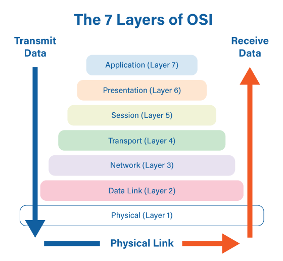
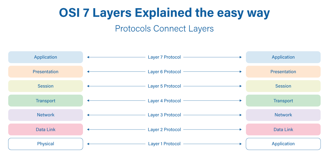
The International Standards Organization (ISO) developed the Open Systems Interconnection (OSI) model. It divides network communication into seven layers. In this model, layers 1-4 are considered the lower layers, and mostly concern themselves with moving data around. Layers 5-7, called the upper layers, and contain application-level data. Networks operate on one basic principle: "pass it on". Each layer takes care of a very specific job, and then passes the data onto the next layer.
Layer 1: The Physical Layer
Starting at the bottom layer of the OSI Model is the Physical Layer. The Physical Layer specifies the hardware means of sending and receiving data on a carrier, including defining cables, cards and physical aspects. Fast Ethernet, RS232, and ATM are protocols with physical layer components.
It addresses the physical characteristics of the network. This includes the types of cables used to connect everything together. The types of connectors used, how long the cables can be, and so on. For example, the Ethernet standard for 100BaseT cable specifies the electrical characteristics of the twisted-pair cables, the size and shape of the connectors, the maximum length of the cables.
The Physical Layer also specifies the electrical characteristics of the signals used to transmit data over cables from one network node to another. There is not any particular meaning to the signals other than what the binary characteristics of what a ‘0’ or a ‘1’ looks like. The OSI model upper layers will assign meanings to the bits transmitted at the Physical Layer.
One very important type of Physical Layer device used in networks is a Network TAP. A Network TAP is a hardware device that is used to copy the traffic on a network link and redirect the copy to troubleshooting and analysis tools without interrupting traffic flow or introducing a point of failure even if the TAP loses power.
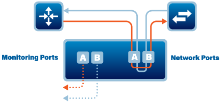
As you can see from the drawing, the eastbound traffic is directed out to Monitor port A and the westbound traffic is directed out to monitor port B.
☑ Layer 1 Physical examples include Ethernet, FDDI, B8ZS, V.35, V.24, RJ45.
Layer 2: The Data Link Layer
The Data Link Layer is where we start to give meaning or intelligence to what we are going to send over the network. The protocols on the Data Link Layer resolve such matters as the size of a packet to send, a way to address each packet to be delivered so that it gets to the intended receiver, and a way to insure that no more than one node tries to send a packet to the receiver at the same time.
The Data Link Layer provides for error detection and correction to make sure that the data sent is the same as the data that was received. If an error is not correctable, the data-link standard needs to specify how the node is to be told of the error so that it can retransmit the data that was in error.
Each node (Network Interface Card - NIC)has an address at the Data Link layer called the Media Access Control address commonly referred to as the MAC Address. This is the actual hardware address, which is assigned by the manufacturer of the device. You can find the MAC Address of your device by opening a command window and running the ‘ipconfig /all’ command.
☑ Layer 2 Data Link examples include PPP, FDDI, ATM, IEEE 802.5/ 802.2, IEEE 802.3/802.2, HDLC, Frame Relay.
Layer 3: The Network Layer
Layer 3 is responsible for routing network messages through the network. An important function of the Network Layer is logical addressing. Each network device has a physical address called the MAC address (See Layer 2). When you buy a NIC for your computer, the MAC address of that card cannot be changed. However, if you want to use some other addressing system, to refer to your computers and other devices, the Layer 3 Network Layer is where you can set up what is called the ‘logical address’. A logical address gives a network device a place where it can be accessed on the network using an address that you assign.
Logical addresses can be created and used by the Network Layer protocols such as IP or IPX. The Network Layer protocol translates logical addresses to MAC addresses.
For example, if you use IP as the Network Layer protocol, devices on the network are assigned IP addresses such as 107.210.76.30. Because the IP protocol operates on Layer 3 to actually send packets, IP needs to translate the IP address of a device to the correct MAC address. You can use the ‘ipconfig /all’ command to find the IP address of your computer or other device.
Once the IP address is resolved we now need to set up the route to take to move the packet to its destination. Routing comes into play when a packet on one network needs to be sent to a computer on another network.
☑ Layer 3 Network examples include AppleTalk DDP, IP, IPX.
Layer 4: The Transport Layer
The Transport Layer is the basic layer at which one network computer communicates with another network computer. The Transport Layer is where you’ll find one of the most popular networking protocols, Transmission Control Protocol (TCP). The main purpose of the Transport Layer is to ensure that packets move over the network reliably and without errors. The Transport Layer does this by establishing connections between network devices, acknowledging the receipt of packets, and resending packets that aren’t received or are corrupted when they arrive.
In many cases, the Transport Layer protocol divides large messages into smaller packets that can be sent over the network efficiently. The Transport Layer protocol reassembles the message on the receiving end, making sure that all packets contained in a single transmission are received and no data is lost.
☑ Layer 4 Transport examples include SPX, TCP, UDP.
Layer 5: The Session Layer
The Session Layer establishes, manages, and terminates the connections between network nodes. A session must be established before data can be transmitted over the network. The Session Layer makes sure that these sessions are properly established and maintained. It provides for full-duplex, half-duplex, or simplex operation, and establishes check-pointing, adjournment, termination, and restart procedures. The OSI model made this layer responsible for graceful close of sessions, which is a property of the TCP protocol, and also for session check-pointing and recovery, which is not usually used in the Internet Protocol Suite. The session layer is commonly implemented explicitly in application environments that use remote procedure calls.
☑ Layer 5 Session examples include NFS, NetBios names, RPC, SQL.
Layer 6: The Presentation Layer
The Presentation Layer is responsible for converting the data sent over the network from one type of representation to another. For example, the Presentation Layer can apply sophisticated compression techniques so fewer bytes of data are required to represent the information when it’s sent over the network. At the other end of the transmission, the Transport Layer then de-compresses the data.
This layer provides independence from differences in data representation (e.g., encryption) by translating from application to network format, and vice versa. The presentation layer works to transform data into the form that the application layer can accept. This layer formats and encrypts data to be sent across a network, providing freedom from compatibility problems. It is sometimes called the syntax layer.
☑ Layer 6 Presentation examples include encryption, ASCII, EBCDIC, TIFF, GIF, PICT, JPEG, MPEG, MIDI.
Layer 7: The Application Layer
The highest layer of the OSI model, the Application Layer, deals with the techniques that application programs use to communicate with the network. The name of this layer is a little confusing because application programs (such as Excel or Word) aren’t actually part of the layer. Rather, the Application Layer represents the level at which application programs interact with the network, using programming interfaces to request network services. One of the most commonly used application layer protocols is HTTP, which stands for HyperText Transfer Protocol. HTTP is the basis of the World Wide Web.
☑ Layer 7 Application examples include WWW browsers, NFS, SNMP, Telnet, HTTP, FTP.
